

In December, 2016 K2FF and I decided it was time to add a decent Top Band antenna to the NA5NN contest station. Glenn had recently installed a 160M inverted L at his QTH in Ocean Springs and it was performing quite well. In fact K2FF/W5UE and our partner in crime, John, W4II (now K0XX) had combined for a #2 finish worldwide in our category in the 2016 ARRL 160M CW contest from Glenn’s QTH on his newly installed L. That was all the convincing I needed so we started scouting locations on my property in Lumberton to duplicate what we had done for Glenn.
Prep Work
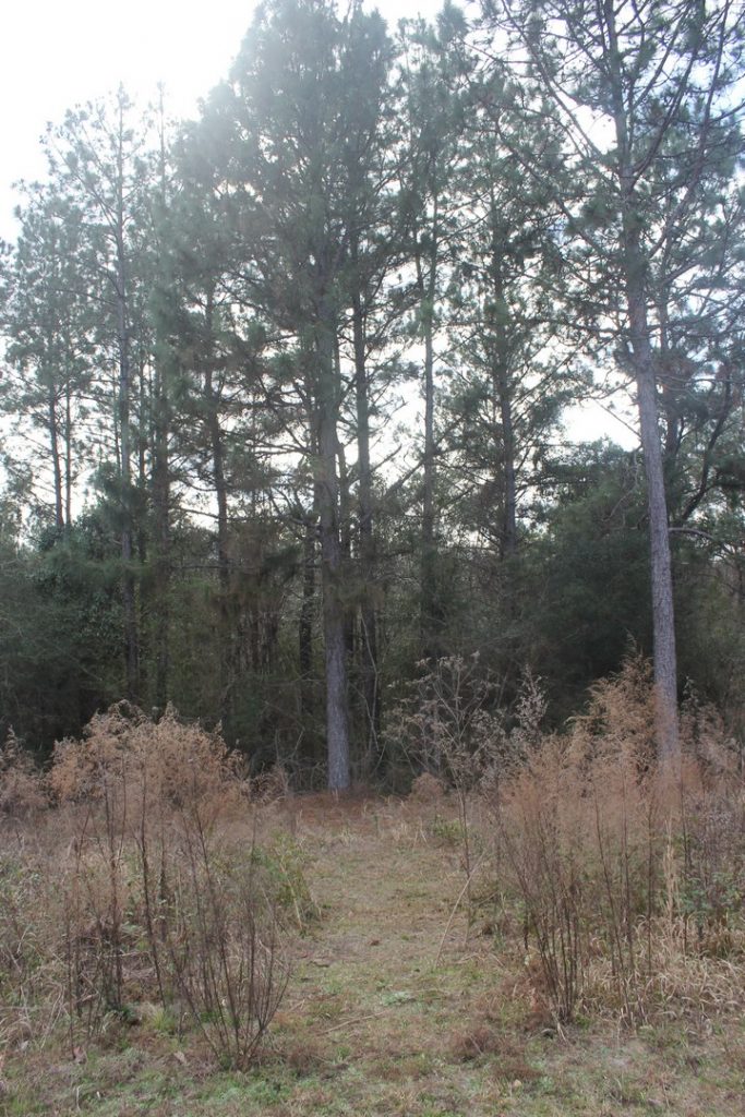
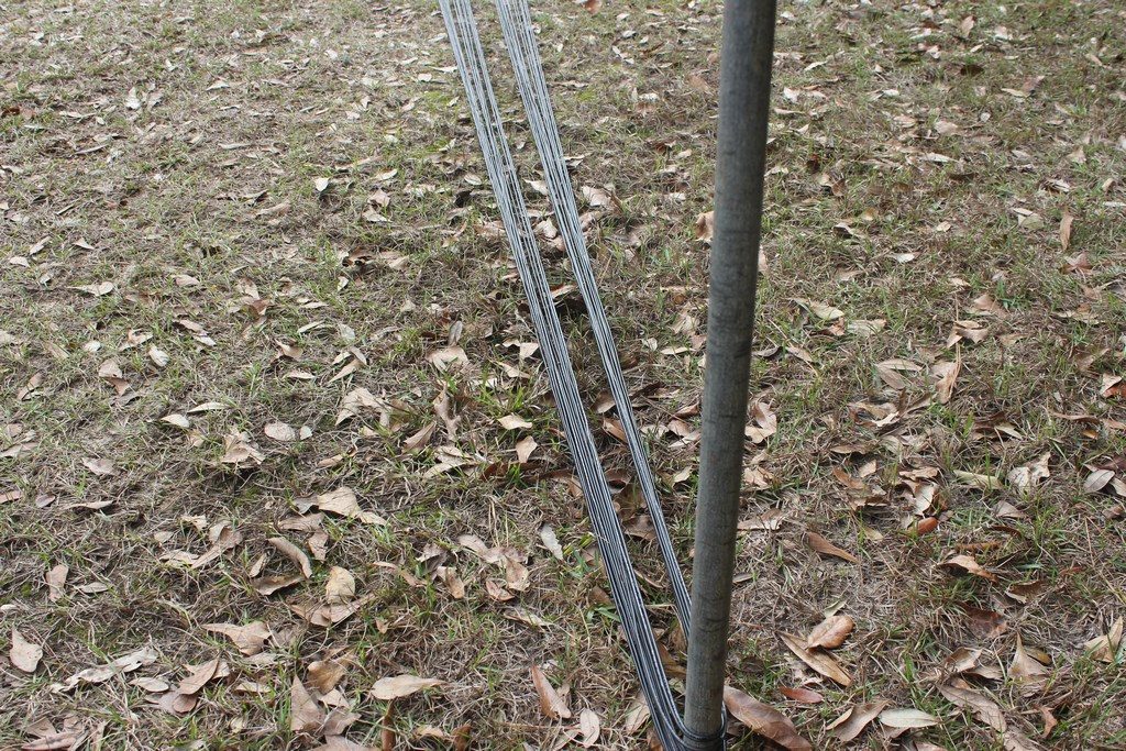
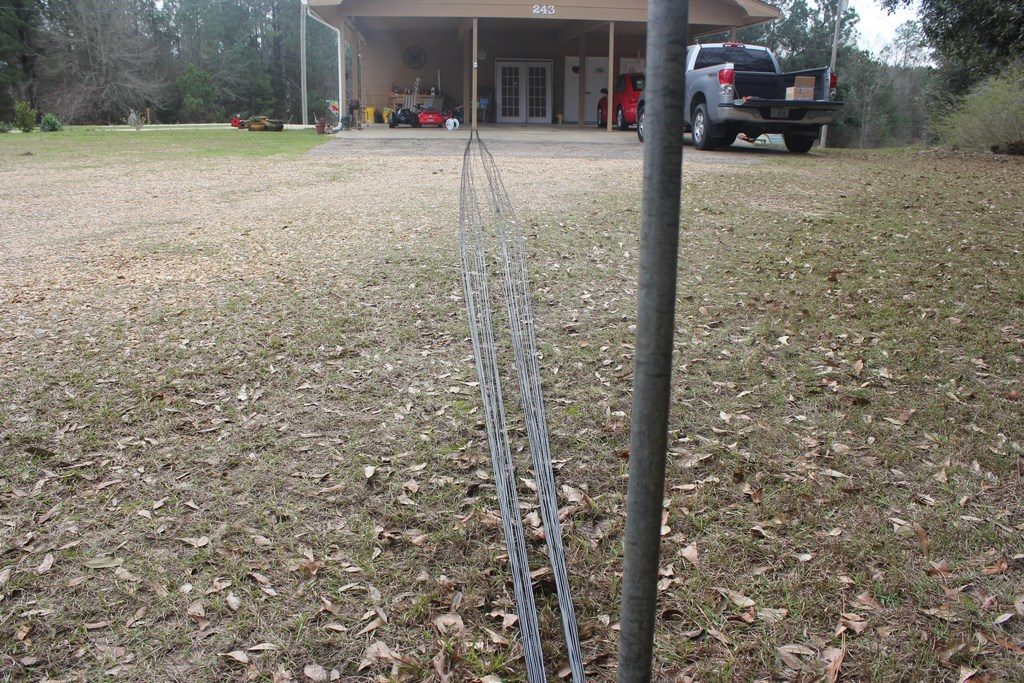
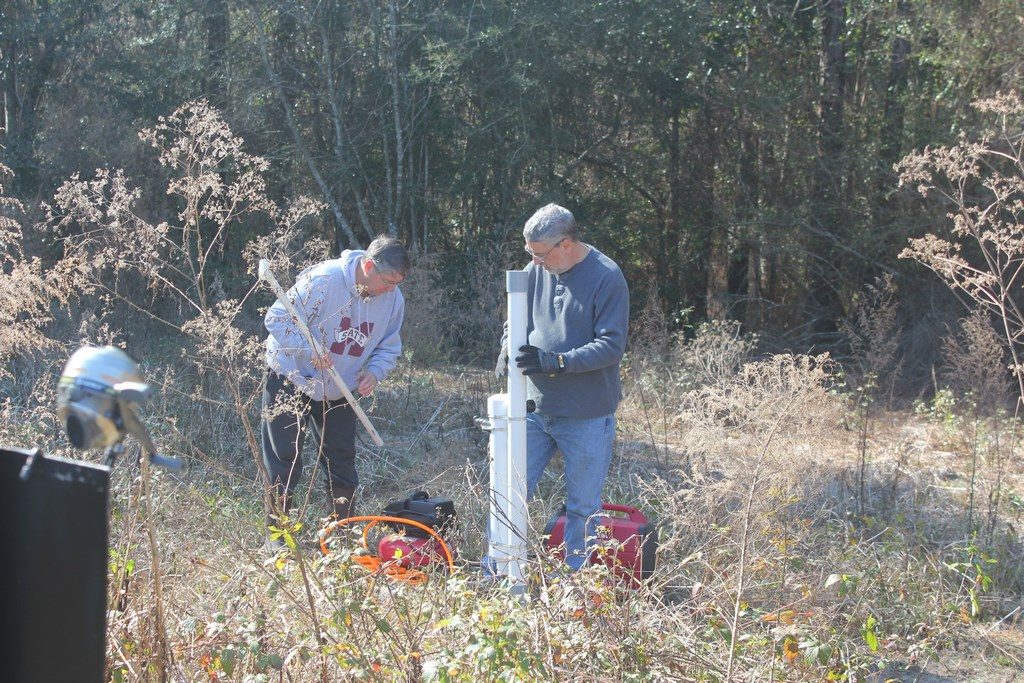
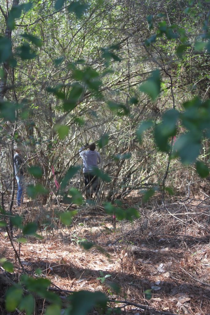
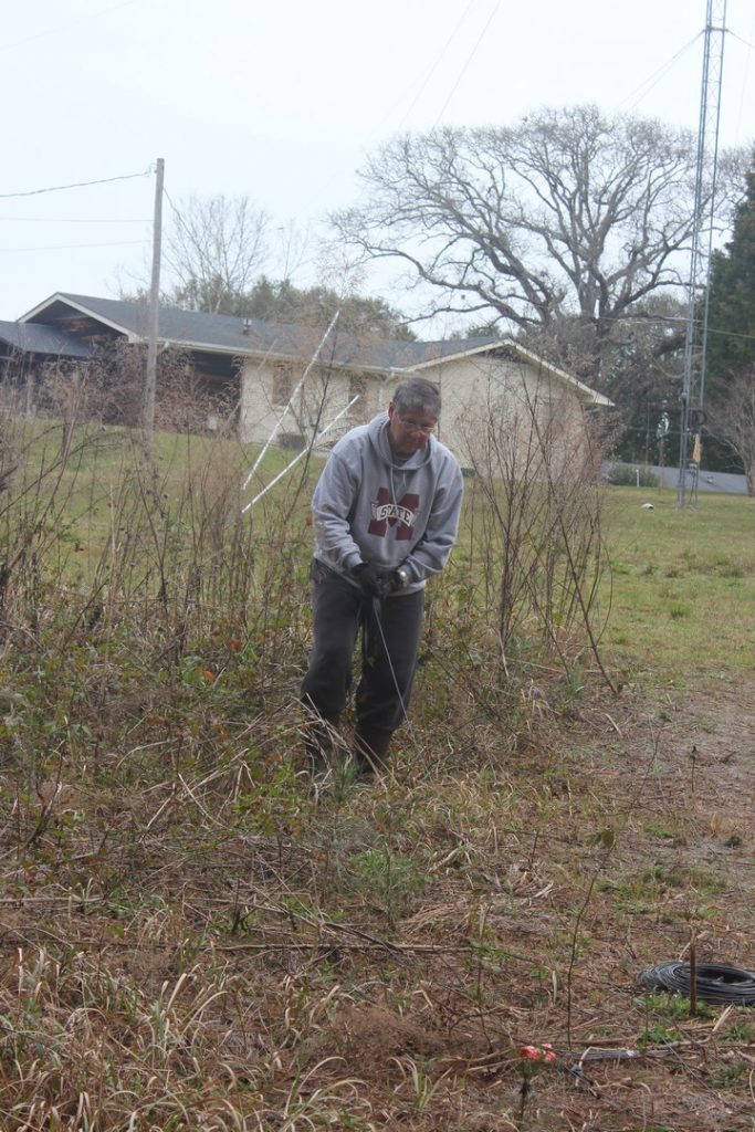
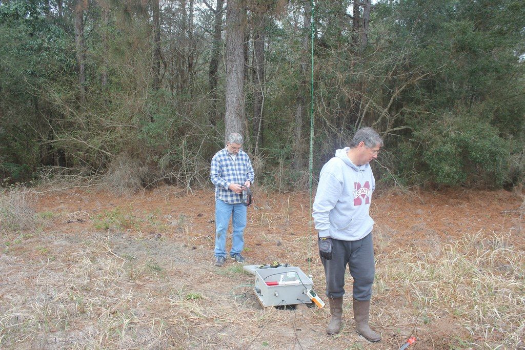
I wanted to put the feedpoint in an area I didn’t keep mowed so that I could simply lay the radials on top of the ground rather than having to bury. The back edge of my property has several large pines and my Rohn 25G tower with Tennadyne T8 is about 120′ away. Our scheme involved shooting a line over one of the pines as high as we could get it and then tied off at the ground. The other end was extended to the top of my tower at about 65′. A pulley would be tied to the Dacron rope above the feedpoint on the ground. This would provide the support structure. The wire for the L would run from the feedpoint, through the pulley forming the vertical component and then the remainder of the wire run over to the tower. Another Dacron rope would be tied to the end of the L wire and that would run through another pulley near the top of the tower and then down to the base. This would allow adjusting tension as well as making length changes fairly easily to make it resonant in either the CW or SSB sub-bands. The pine in the center of the left photo above was our choice. It is about 75′ tall and lines up nicely with the tower.
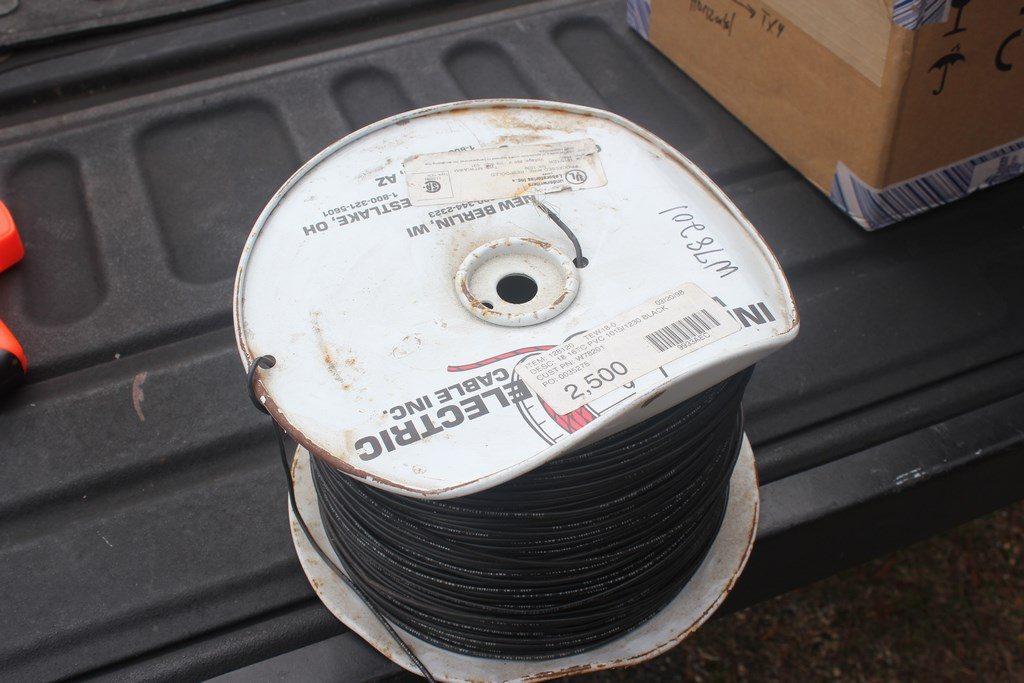
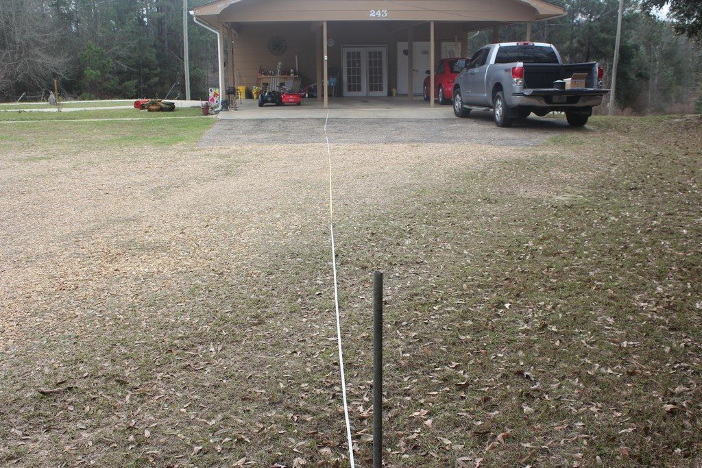

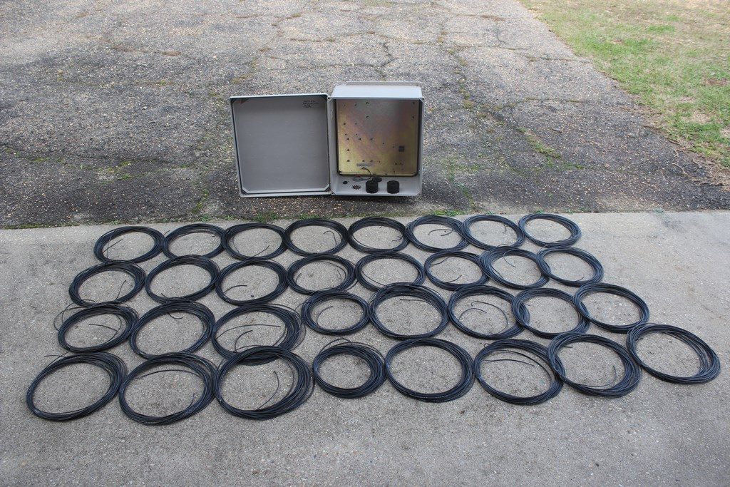
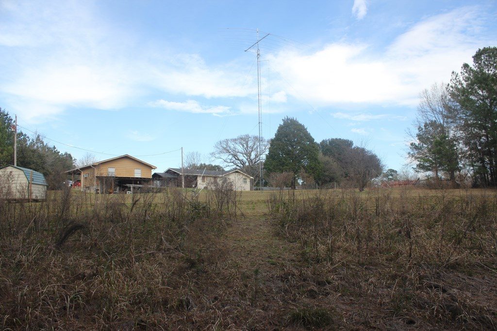
Once we had a plan for where/how we were going to install I set off to prepare the 32 x 65′ radials that would provide the ground-plane. Again, some research indicated that 65′ was a reasonable length and that after 32 you started running into diminishing returns unless your soil has really poor conductivity properties. I started with a 2500′ spool of stranded 18AWG wire I found at a good price on eBay. This wire lays really nice and is easy to handle. Top middle and right photos shows how I used a post on my carport and a pipe driven into the ground 65′ away from the carport post. From here I simply secured the end of the spool to a nail on the carport post and started rolling off wire as I walked around the pipe and then back to the carport post 16 times. The bottom middle photo shows the results of that. From here I just had to cut each wire at the pipe and carport post and I was left with my 65′ radials. The bottom right photo shows them coiled up neatly along with an electrical enclosure box I had salvaged from another ham’s QTH when we were taking his stuff down. The following weekend Glenn came by and we soldered small terminal rings on each end of the radials to make it a little cleaner to attach to the the ground plate in the box and staple down at the ends in the ground using 10″ ground staples to help keep them in place.

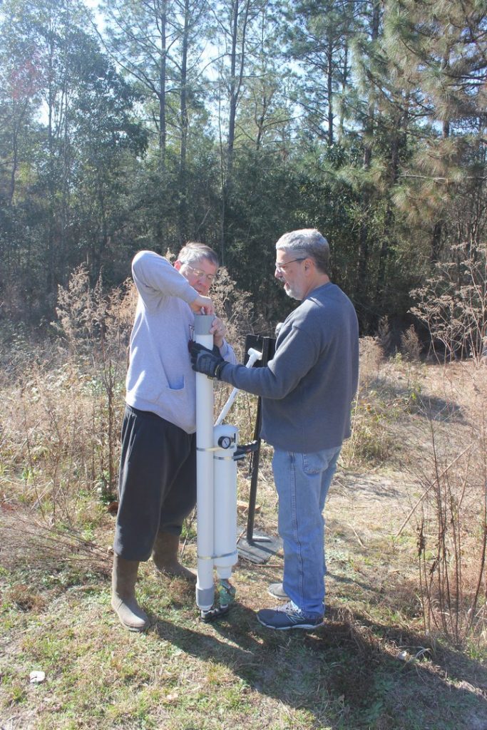
My final bit of prep worked involved getting the feedpoint enclosure ready. This required drilling 32 holes evenly distributed around the perimeter of the aluminum plate and mounting the stainless steel screws with wingnuts that I would use to attach the radials. I fabricated the feedpoint mount from 1″ PVC and some “Ts” and attached each “T” on the ends to the sides of the box with stainless steel screws/nuts. The static bleed inductor slipped right over the PVC. This particular one is available from Array Solutions but there are several examples of homebrew ones on the Internet.
Install Day
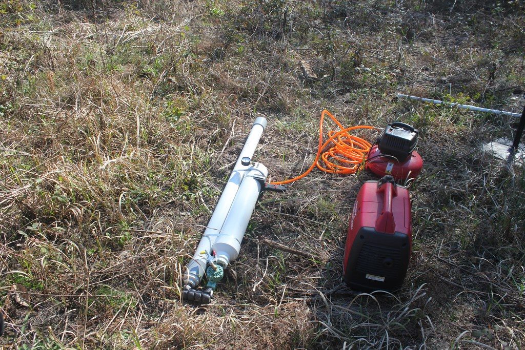

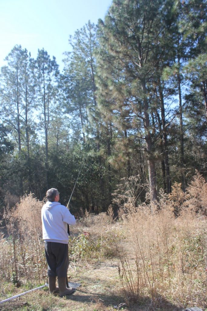
It was a beautiful and fairly brisk February, 2017 morning when Glenn and I decided to tackle the job. First order of business was to get a line over the pine we had selected. The goal was to get it a high as possible in the tree so that we could get as much height as possible for the vertical leg of the “L”. Especially since the tree we were working with was only about 70′ or so at the top. There are several variations of Potato Guns out there in the ham world. The one in the photo to the left above was designed and constructed by one of our club members and great friend, George, N5GH. Pump the extra large air chamber up to about 60 lbs and it will put the tennis ball projectile over just about any tree you can find in south Mississippi. The 70′ tree we were tackling would easily be reached with 40 or so pounds. More than that and we would have been looking for the tennis ball for hours in the woods behind the tree. The bottom 2 photos shows Glenn and I filling up the air chamber and then Glenn loading the tennis ball that has been tied to the end of a line coming off of a fishing reel. You can see the reel in the lower left corner of the top right photo. This light line monofilament line would be shot over first and used to then pull up a slightly heavier string. Finally the string pulls up the Dacron support rope. I used 3/16″.

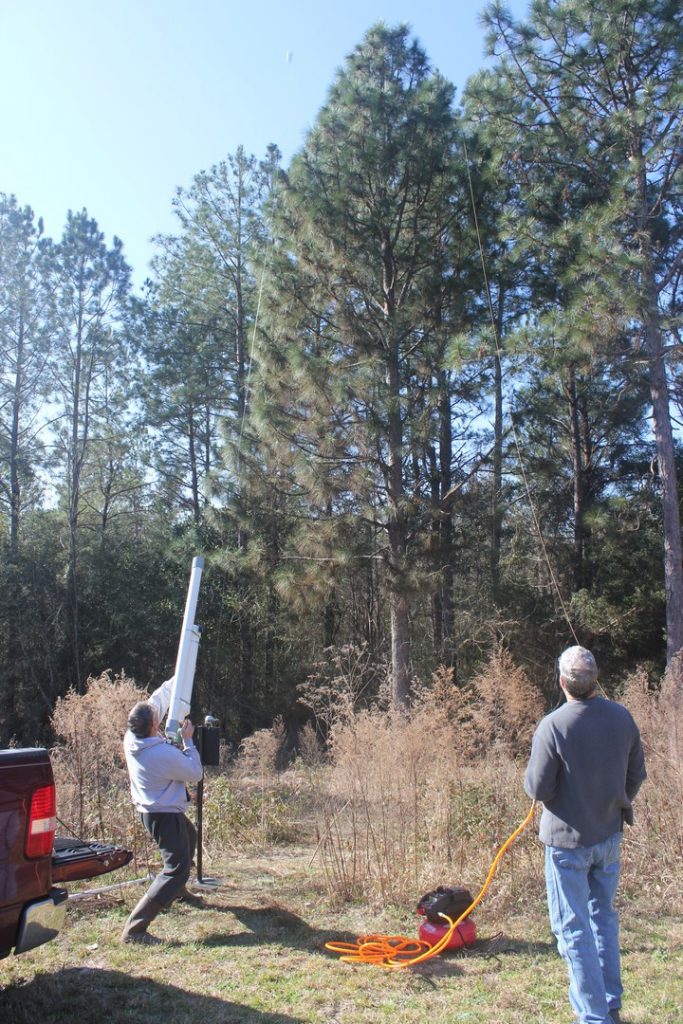
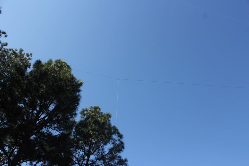
If you look closely in the left photo above you can see our first attempt. This is the string that would be used to pull up the Dacron. However, neither of us was really satisfied with the placement. So, we reloaded and Glenn lined up for another shot… you can still see the first string that appears to be coming out of my head on the right.
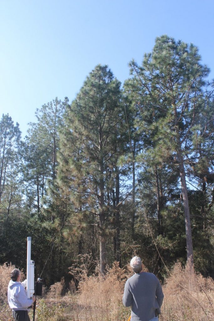
This shot sailed directly over the top of the tree. You can faintly see the fishing line coming from the reel. In the middle photo Glenn and I are off in the woods behind the tree locating the tennis ball. Once that was accomplished and we got our intermediate pull string in place I stayed in the woods feeding the Dacron rope while Glenn pulled from the other side.
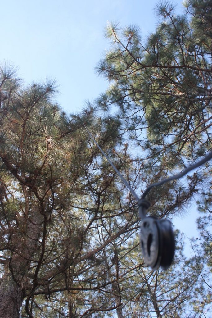
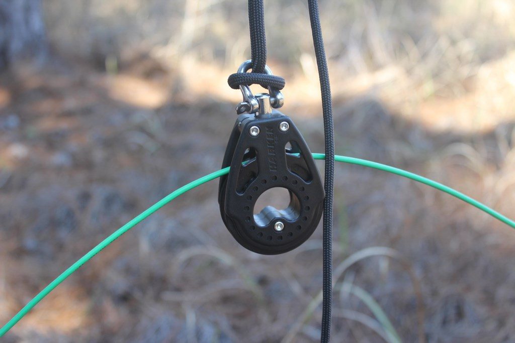


This series of photos shows the process of attaching the pulley at the approximate distance from the tree that the feedpoint box was going to sit and stringing the 135′ of 10AWG stranded wire for the active portion of the antenna through the pulley. On the bottom 2 photos I am on the tower tying off the top support rope. Glenn was on the other end of the rope in the woods and once I had it tied off he started pulling it up. We had temporarily secured both ends of the L wire on the ground at the feedpoint so they wouldn’t end up out of reach. But at this point in the process the rope was still fairly slack with both ends of the wire still on the ground below the pulley. It took a little adjusting back and forth to get the pulley positioned exactly where we wanted it above the feedpoint box.
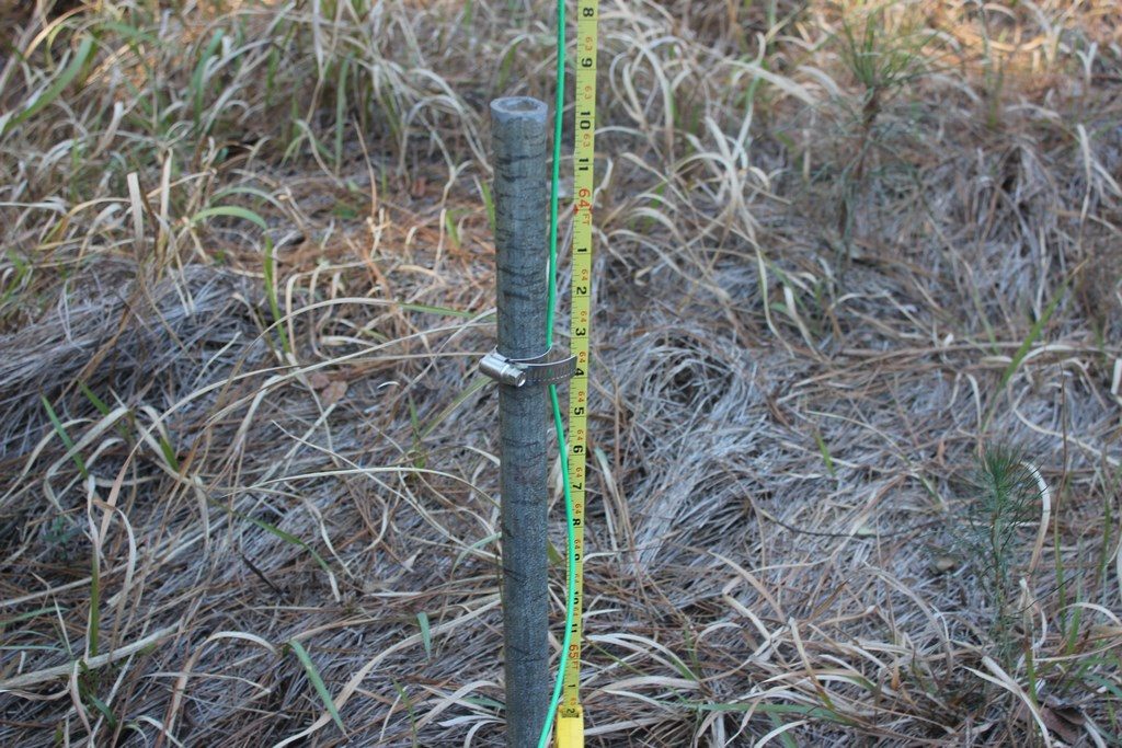
Once we had the support rope about pretty close to where we wanted it we secured the feedpoint end of the wire and also attached the end of a 100′ tape measure to the pulley and pulled it up into position so we could check the vertical element height. As you can see, just over 65′. Not ideal for 160M, but a workable height. We then took down the tape measure and I brought up the rope attached to the horizontal end of the L up the tower and ran it through the pulley I had up there and then down to the tower base. The photo on the right shows the L in its fully raised height.
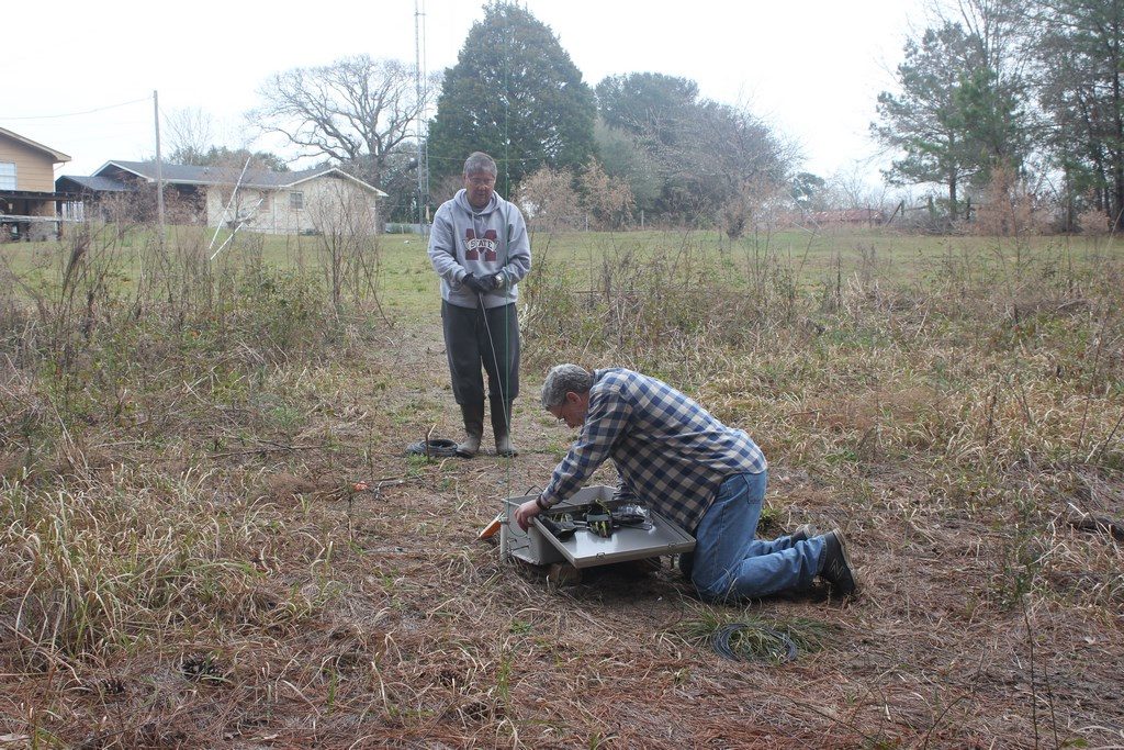
With the L in-place Glenn and I started laying out the radials.
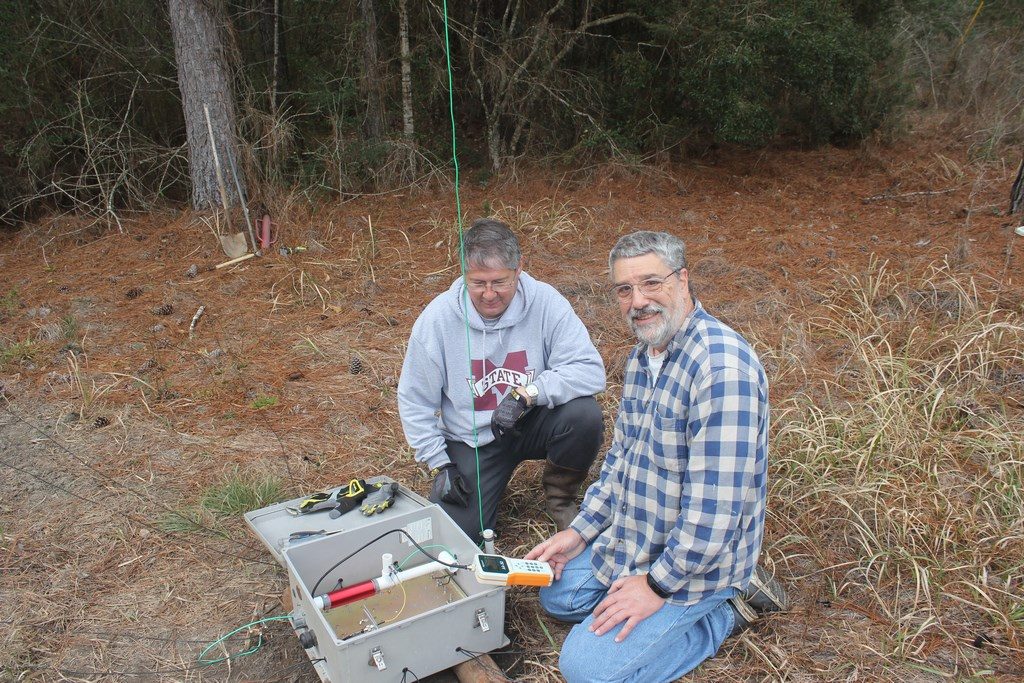
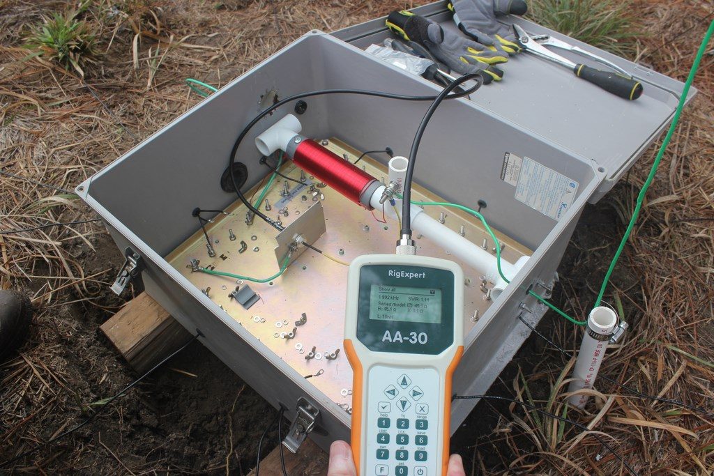
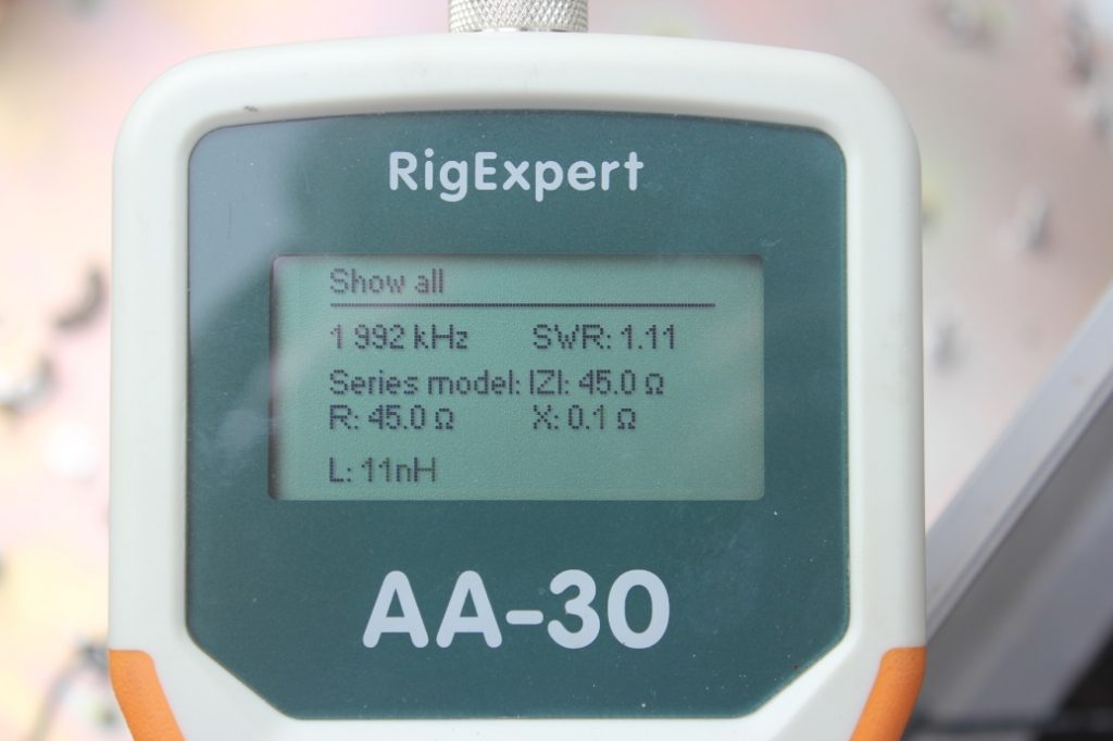
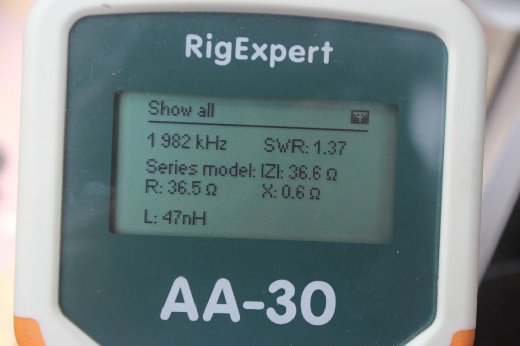
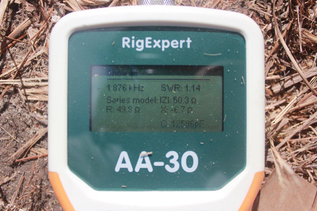
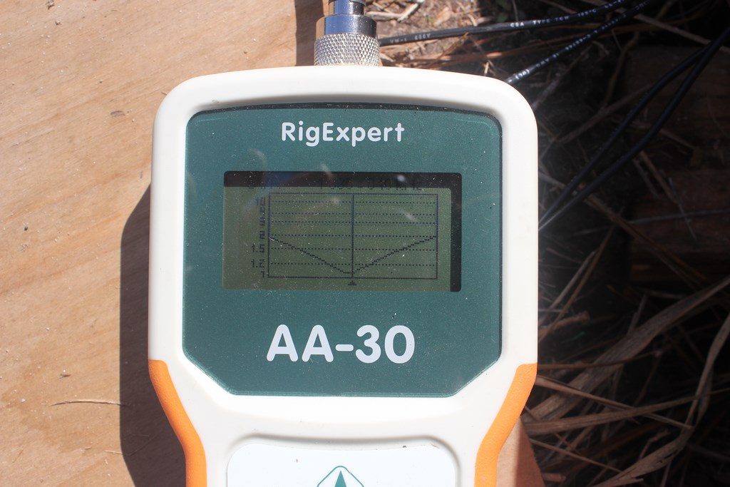
After consulting with John, W4II/K0XX we decided we would do some SWR checks along the way so we could see if we reached a point of diminishing returns on the number of radials before we hit 32. This was the first check with about 4 radials attached to the ground plate. With the length of the L wire the resonant point should have been around 1830 kHz. The AA-30 is a little difficult to read but the low SWR point was about 1992 kHz at 1.1:1. This was fairly encouraging to us so we continued adding radials with checks along the way. As expected, low SWR frequency continued to lower as we added more radials, but, we did notice that impedance was lowering as well, driving the SWR up steadily.
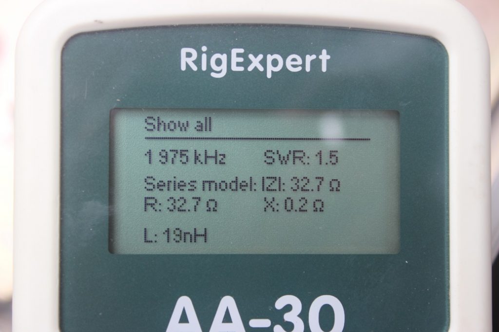
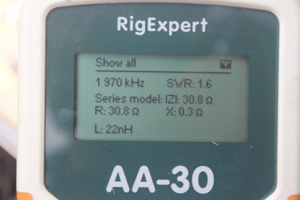
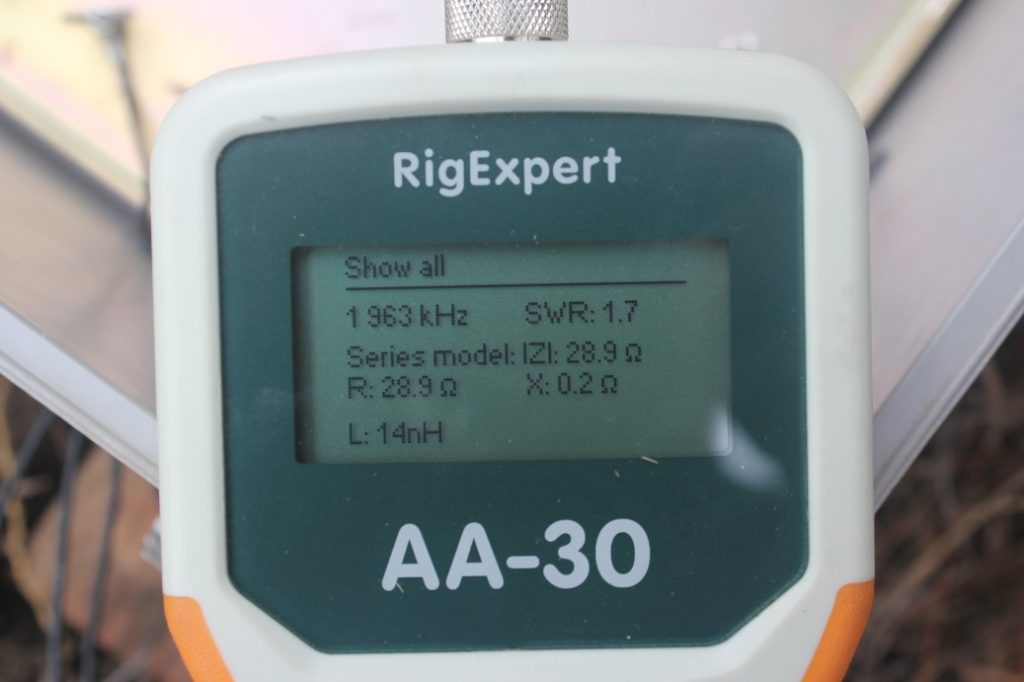
This is seen above. At 4 radials we had a pretty good match at the feedpoint but with the L wire length cut for about 1830 kHz it was apparent something was still a little off, especially as we added the additional radials. We could have tried to address this by adding length to the L to try and get a better match in the CW segment but we first decided to consult with John, K0XX (ex W4II) for his opinion. John suggested we try adding a shunt coil to the feedpoint to see what would happen. He did some quick calculations and recommended a starting point for the coil.
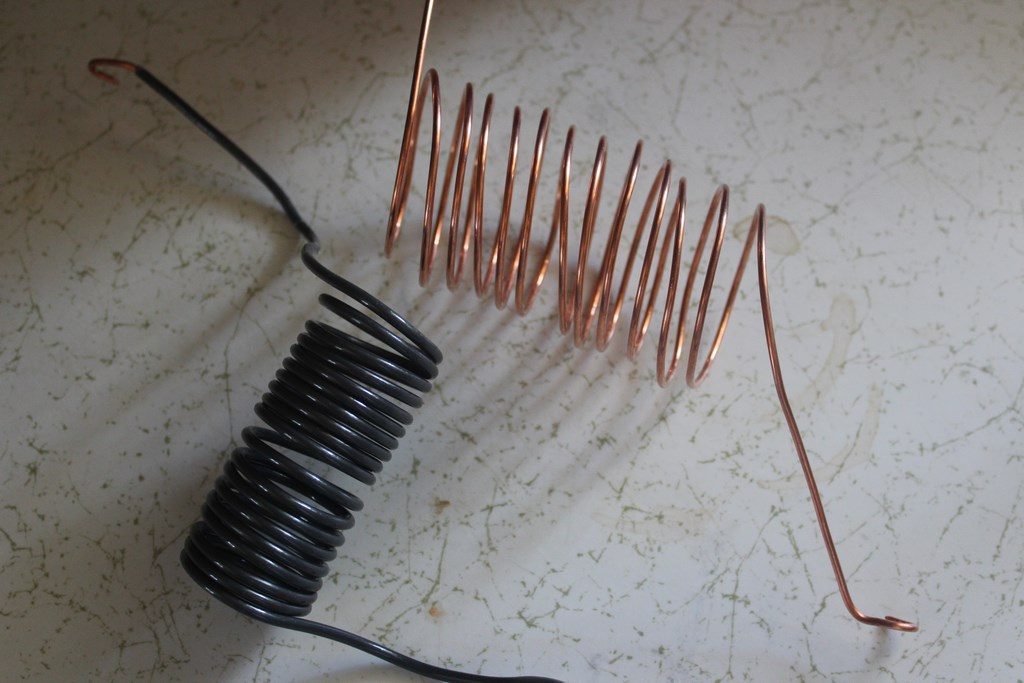
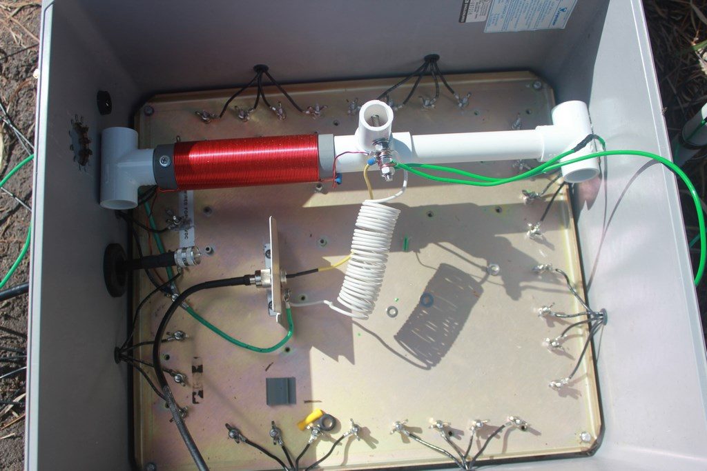
Photo on the left shows a few of my initial attempts. Neither of these helped, and in fact made things much worse. John encouraged me to keep experimenting with more/less turns, different diameter, etc. The version in the photo on the right ended up being the winner. It’s about 30 turns of 12AWG solid copper wire (stripped from a piece of Romex). I used a 1.5″ piece of PVC to wind the coil on.
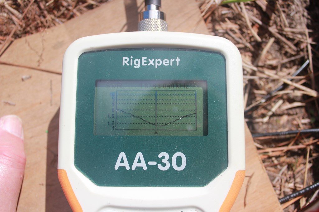

The top two photos shows the readings with the L wire set to the SSB point and lower two photos show the full length L wire cut for CW. As you can see, good impedance and excellent SWR curves. To switch from CW to SSB is simply a matter of opening the feedpoint box, loosening the L wire from its support pipe and then attaching either the end of the wire or a pre-marked/stripped point a few feet up the wire to the connection point screw in the box. If you look closely in the photo in the box in the previous photo set above you can see the excess wire hanging in the box. This has the antenna tuned for the SSB sub-band. Since I am primarily a CW op I usually keep the antenna set for CW and use the tuner for the occasional SSB Top Band DX station I might need. When configuring the station for a Top Band SSB contest we’ll make the change in the box to SSB.
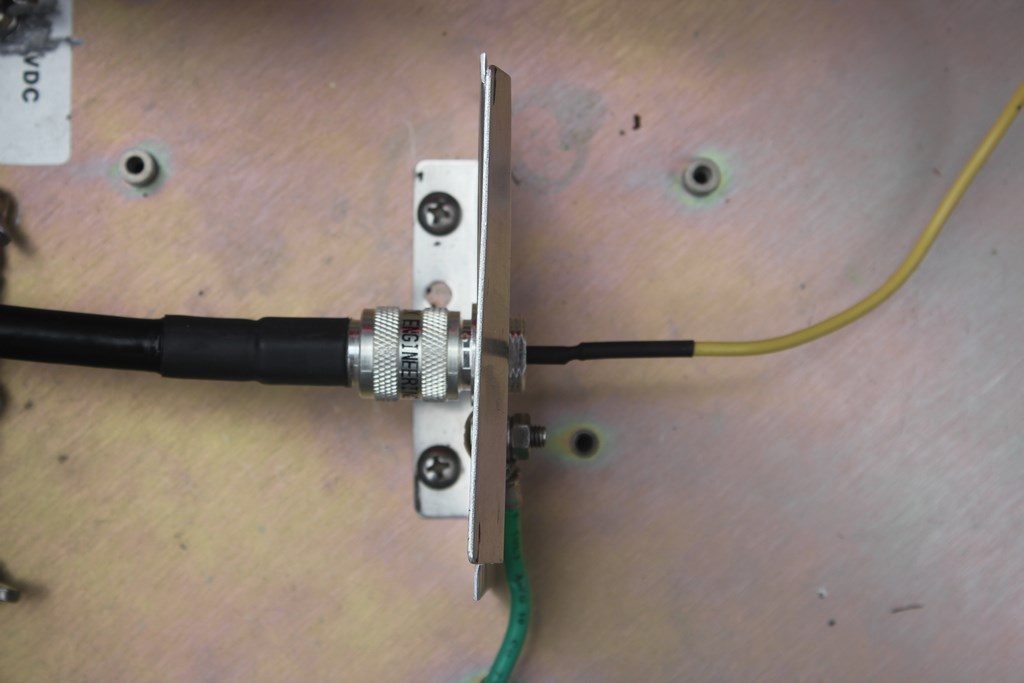
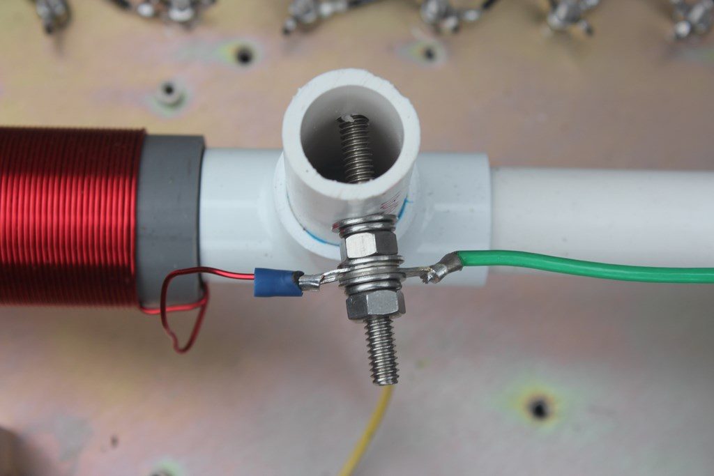
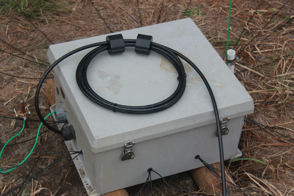
These final photos show closeups of the coax connection point inside the box as well as the wire feedpoint connections. The final photo on the right shows the box all buttoned up. The antenna is fed with RG-213 and I made a common mode choke at the feedpoint using two of KF7P’s Biggest Clamp-on #31 mix toroids and about 3 turns of the feedline.