

In March, 2017 I decided to add the Elecraft KPA500 amplifier to my primary station. I wanted something fully integrated with the K3 and more “moderate” power for casual operating. Photos and text below documents that build. I opted for the kit version since I enjoy hands-on projects and, as usual with Elecraft, the KPA500 is an easy build, more mechanical than electronic with its pre-assembled PCBs. The instructions are excellent, clear, and very thorough.
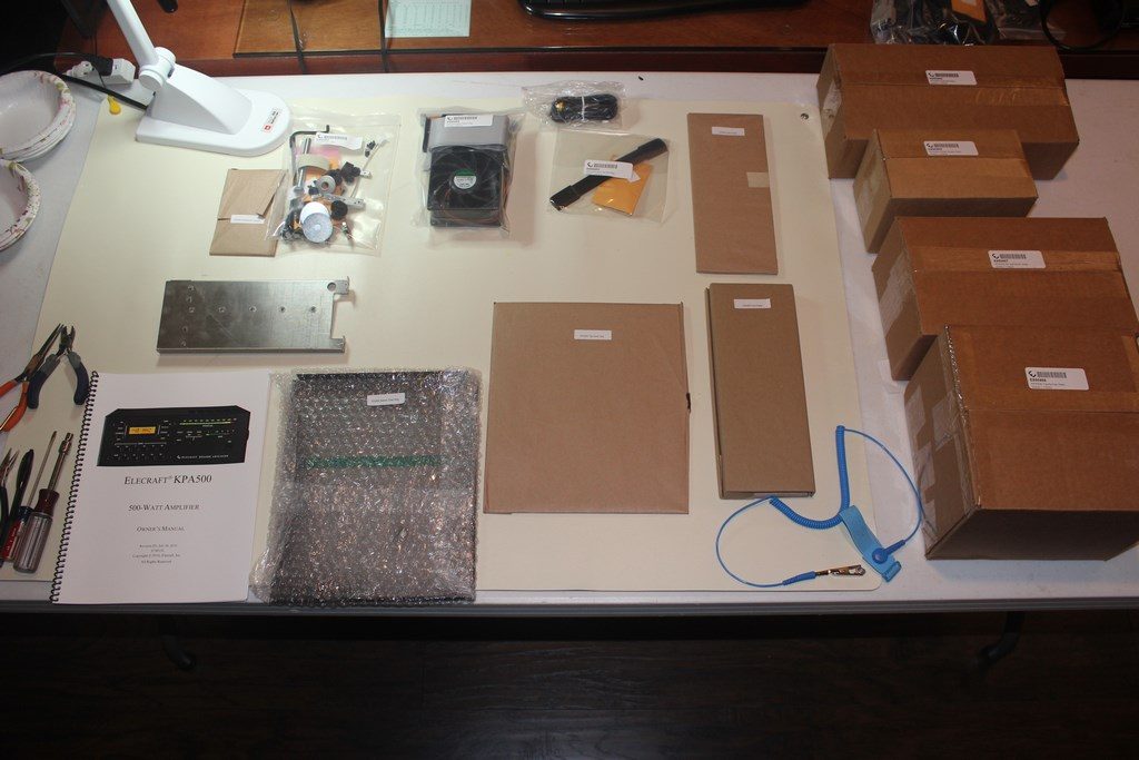
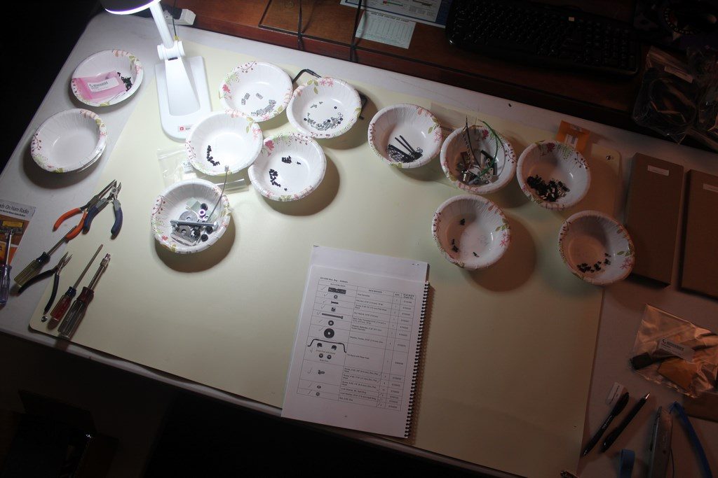
As with any kit project the first step is to get everything out of the box and do an inventory. I find the small paper bowls are good for sorting small parts and aids with the counting of screws and such. This is the same approach I use for any kit and it works for me. Anti-static mat was used on my work table.
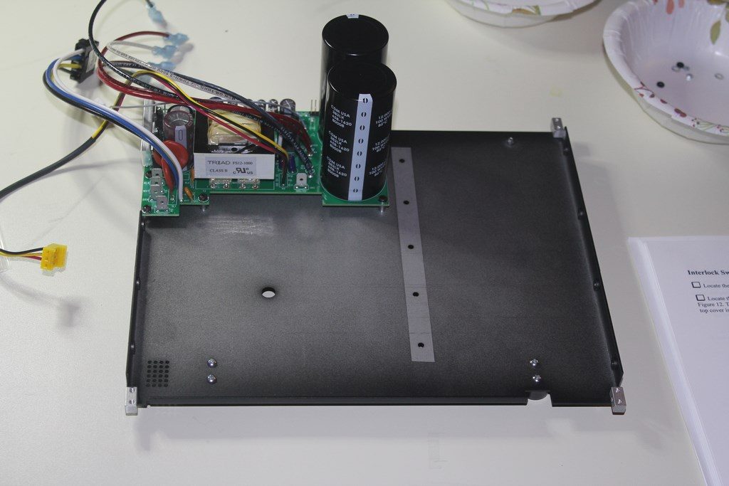

After attaching the tilt stand, feet and 2D fasteners to the bottom cover the next order of business was to prepare and mount the Power Supply Module. The prep step involves installing an insulating film on U3 then mounting the heat sink bar. The instructions say the resistance between the metal tab on U3 and the heat spreader should be 5K ohms or greater. My measurement was ~8K ohms. In preparing the side panel I found that the “twist method” of getting the rubber feet mounted worked just fine if you took your time with it.

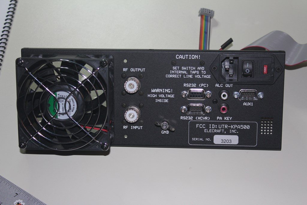
Mounting of the fan, RF in/out SO-239 connectors, terminal strip, main power entry module and I/O module on the back panel was very straight forward with no surprises.
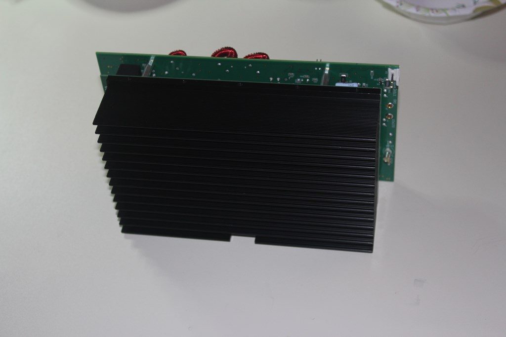
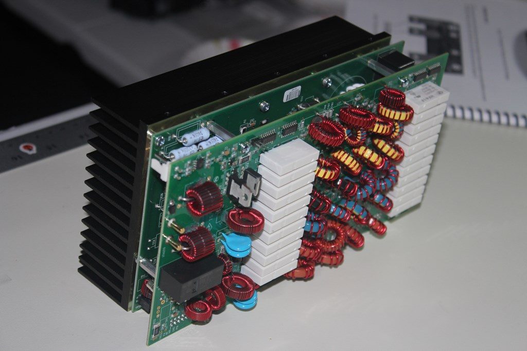
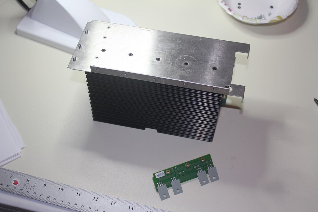
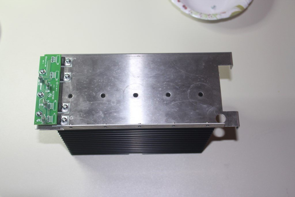
Assembly of the PA/LPF Module was next. This step consists of mounting the Z bracket and rectifier board onto the module. Making sure the rectifiers are not shorted to the PA module is an important step here.
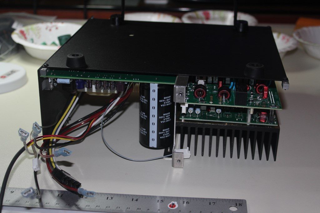

The above steps show mounting the PA/LPF module to the bottom panel and then installing the right side panel. Also in this sequence the transformer support plate was attached to the bottom panel.
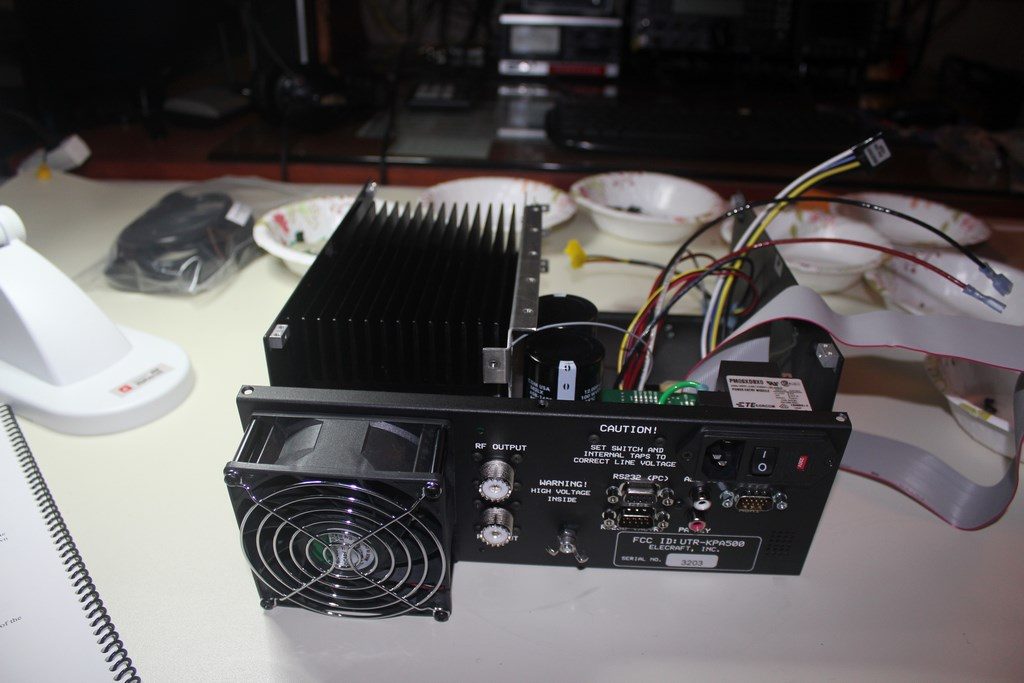
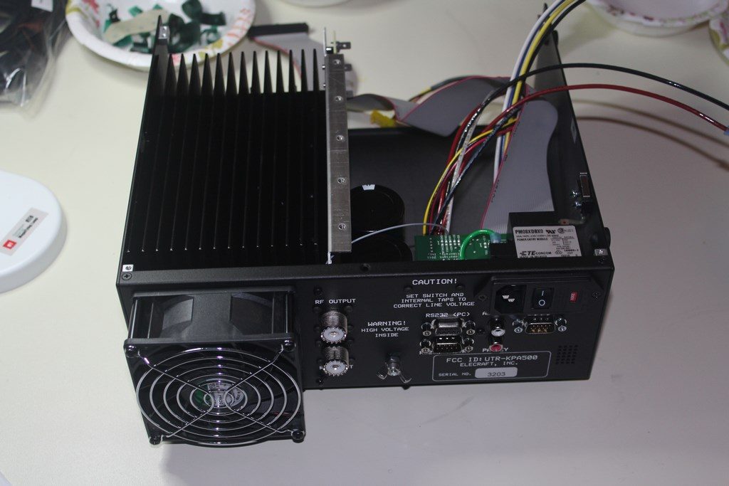
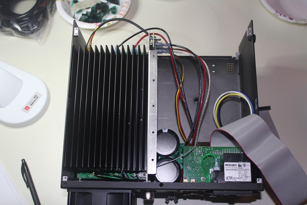
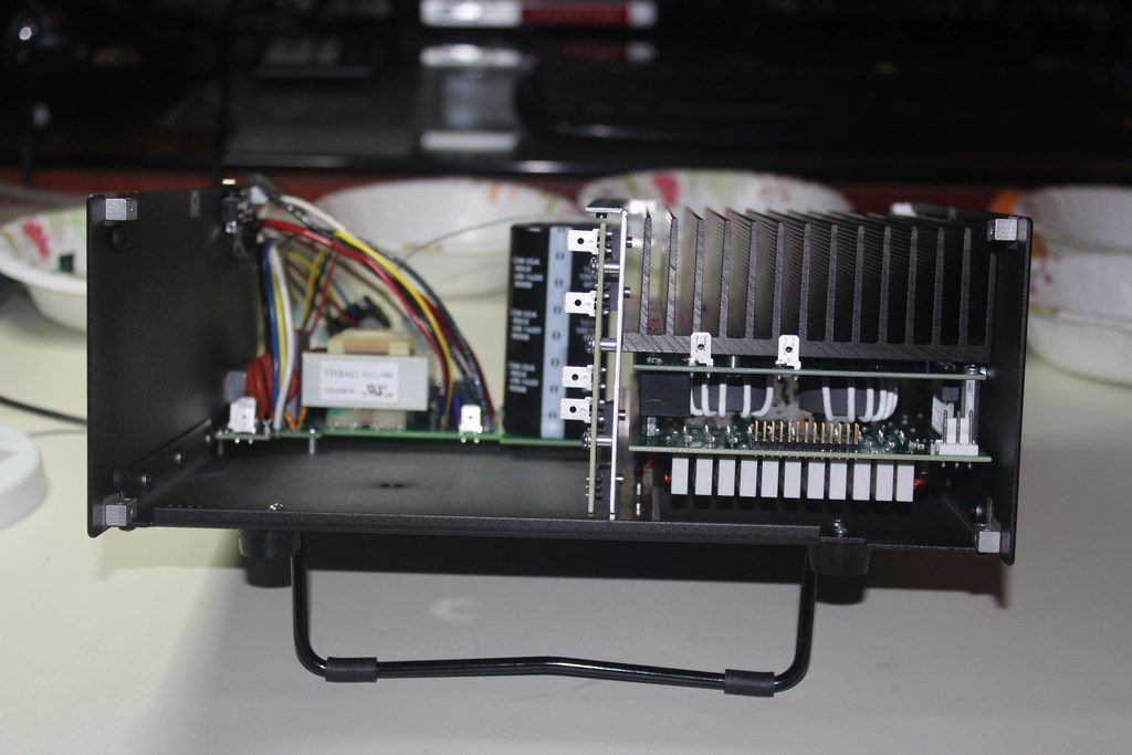
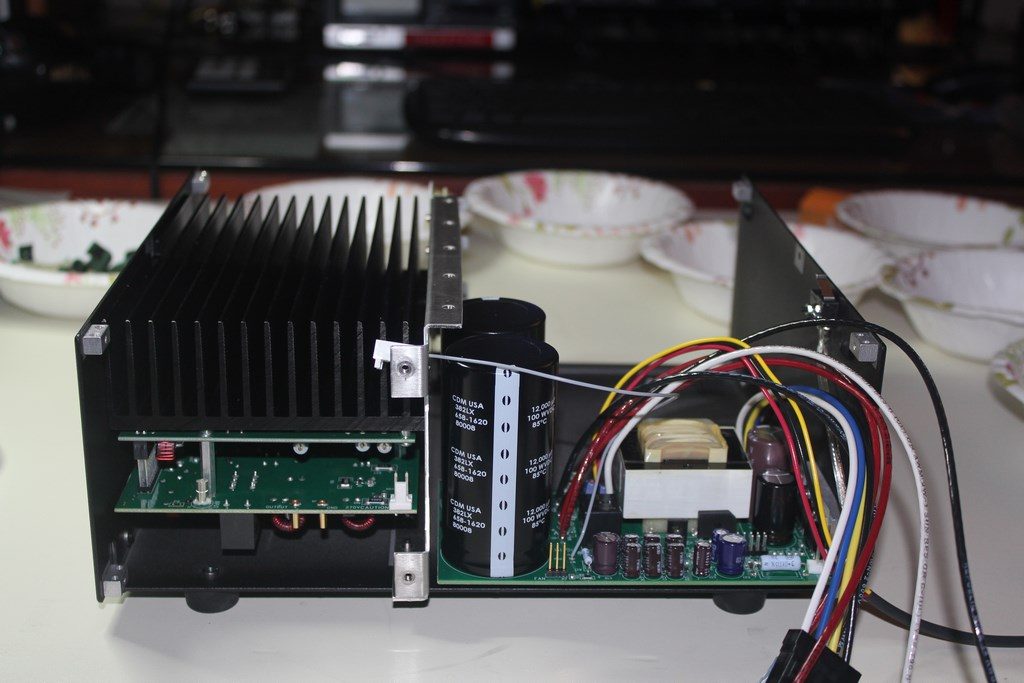
Next up is attaching the back panel to the chassis. Before attaching the back panel make sure you have plugged in the 270V wire and interlock switch cable. You can’t really reach those once the back panel is mounted. With the back panel positioned as in the top left photo you attach several wires and cable assemblies to the PA and power supply modules. Follow the manual closely (always!). Bottom left photo above shows the back panel being attached to the chassis. There are a few checks in this step to make sure that the grey wire connected to the RF output connector. The pin on the grey wire should not be touching the Z-bracket. Also make sure no wire will interfere with fan motion. Bottom right photo shows this step completed with power supply wiring attachments made.
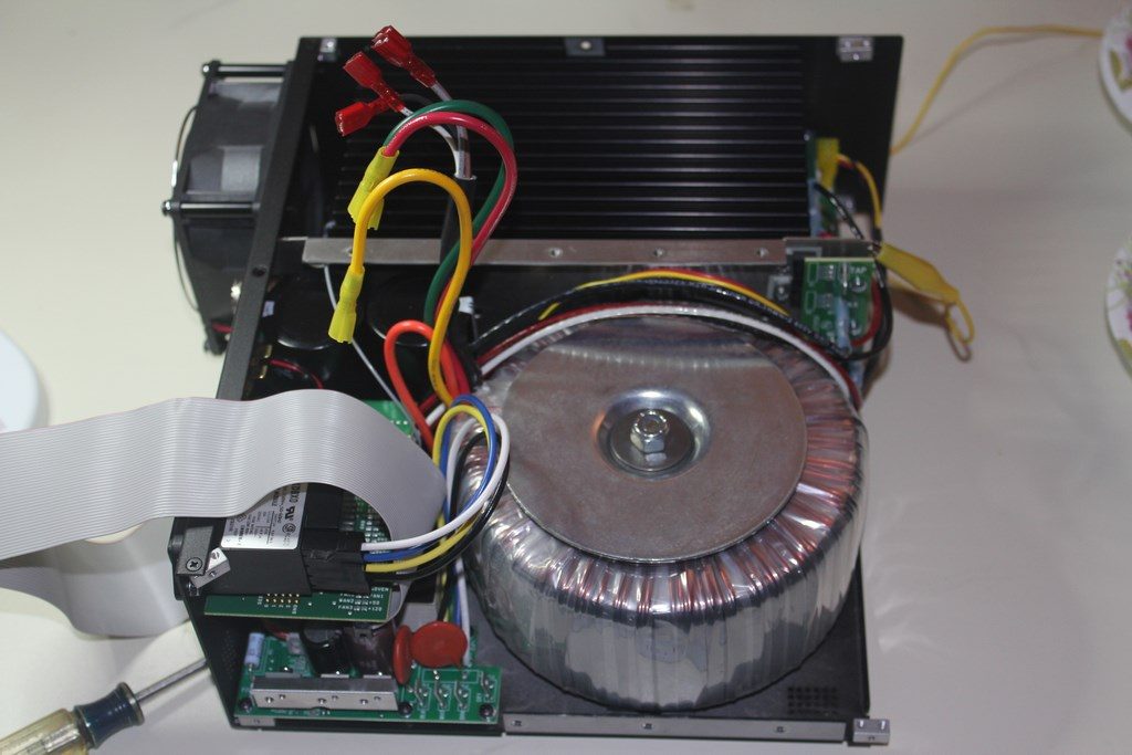
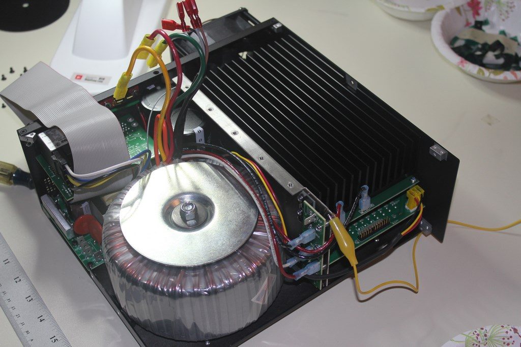
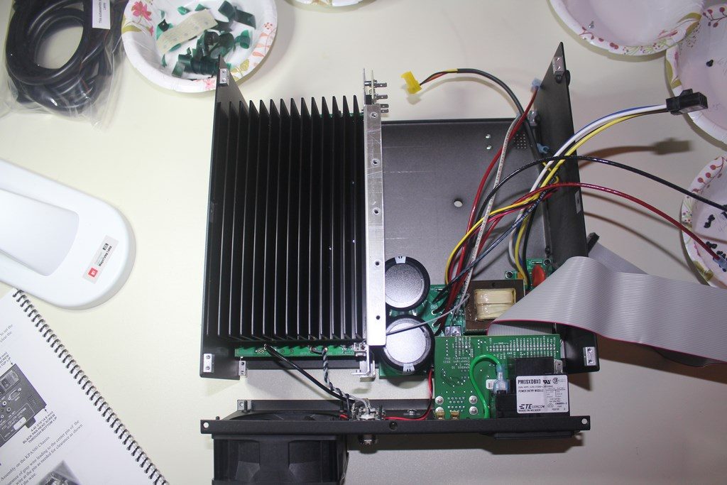
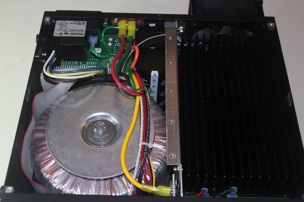
Unfortunately I didn’t take any photos of installing the transformer mounting bolt, rubber disk and bumpers. To get the transformer in-place the left side panel is removed. It did take a bit of shifting the transformer around some once it was over the mounting bolt to get it to sit snugly against the rubber bumpers and laying uniformly on the bottom rubber disk. The yellow alligator clip attached to the chassis in the top right photo was going to my ground point on the anti-static mat. Bottom right photo shows the main chassis with all of the wiring buttoned up and ready to mount the front panel.

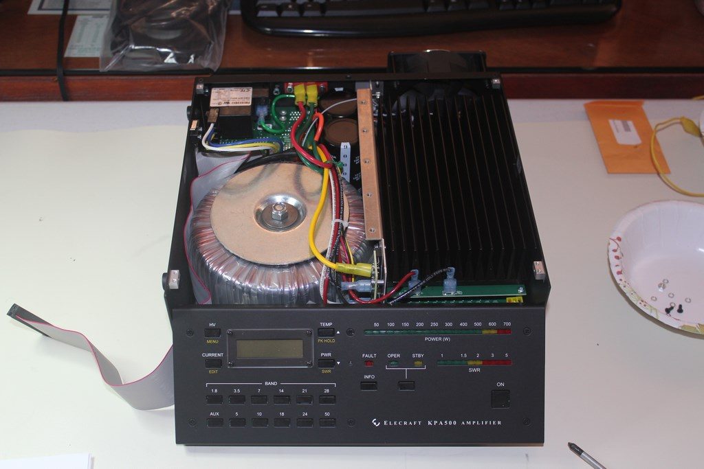

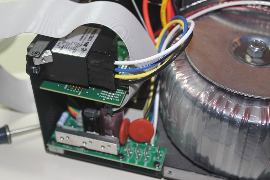
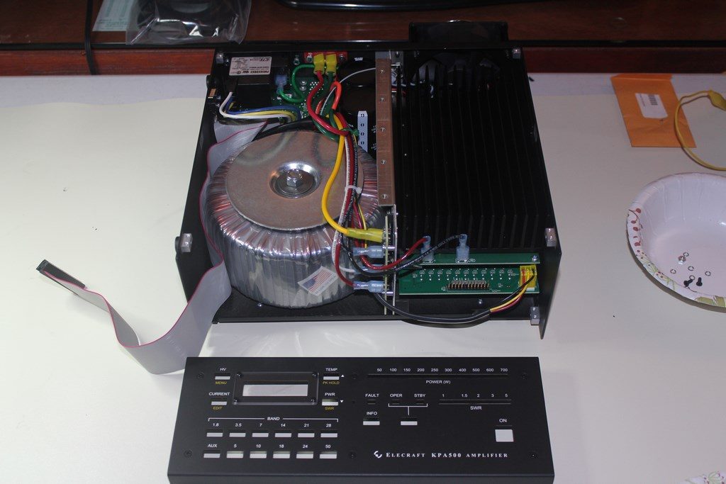
I wore the wrist strap attached to my ground point any time I was handling the front panel PCB. It is off in the top left photo to underscore its importance and also so I could handle the camera. Mating up the PCB and from panel was a little tricky for me. The manual mentions LED alignment might need to be adjusted and this was definitely the case. The tolerances are tight and one or two just a little out of line will prevent a clean fit. Take your time and don’t force anything. There are 2 ribbon cables going from the front panel PCB to the main chassis. When you are putting the front panel assembly in place and attaching watch the path of the long ribbon cable. Mine was a few inches longer than needed, and as the manual instructs, I routed the excess between the front panel PCB and transformer. I wired my main power input for 230 VAC according to the instructions in the KPA500 Owner’s Manual. My measured voltage on the 230 VAC circuit I had installed for the amp was 244 VAC. So, I selected the yellow power supply transformer tap. Bottom right photo shows everything in-place and ready for the top panel.
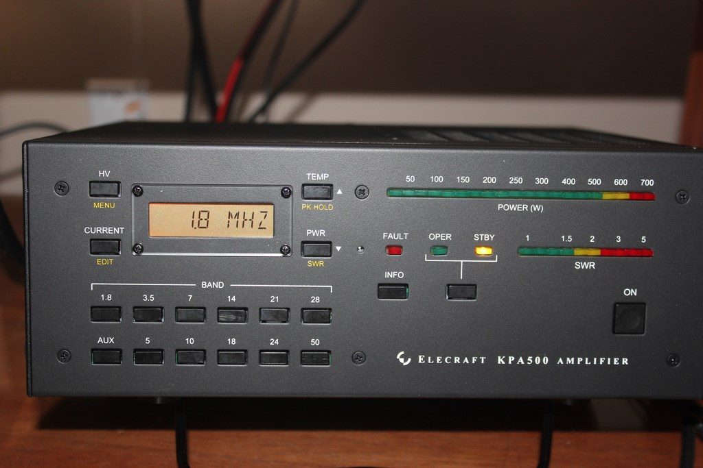
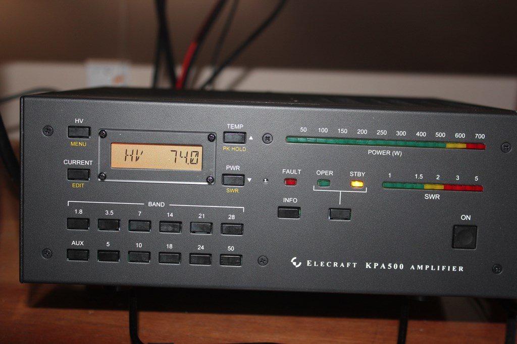

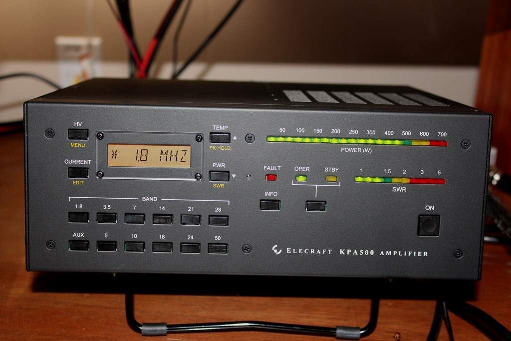
Ready for checkout. After initial power on and no unexpected lights or fault conditions I checked the HV reading as instructed in the Owner’s Manual. It read 74 volts, within the expected range of 65-85 volts indicating the yellow transformer tap was appropriate. Heat sink temp with no RF applied was about 23C, pretty close to the room ambient at the time. After cabling up to the K3 and dummy load I put some RF into it. About 25W in from the K3 yielded just under 500W out, success!! The KPA500 is a great little amp. When fully integrated with the K3 (or other compatible Elecraft transceiver) using the optional KPAK3AUX cable it’s like having a 500W rig. Band changes on the rig are automatically reflected on the KPA500 and visa versa. Tuning is automatic and immediate and the K3(s) is aware of the status of the amp (standby/operate) and allows for separate power settings depending upon this status. So, when the amp is in standby the K3 can be configured for 100W out and when it’s placed into operate power can be set to the appropriate level for full output, usually around 30W for me.