

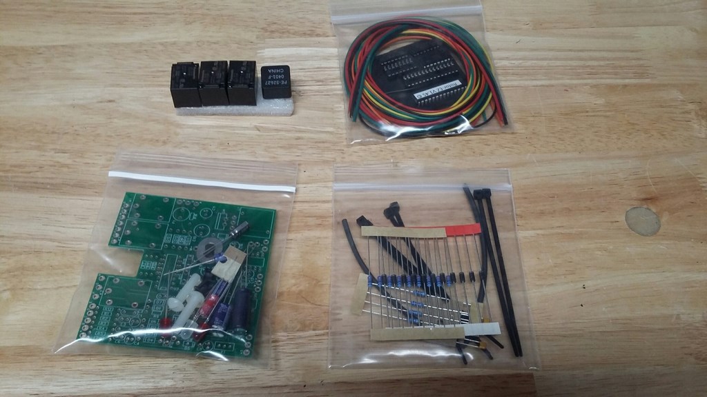
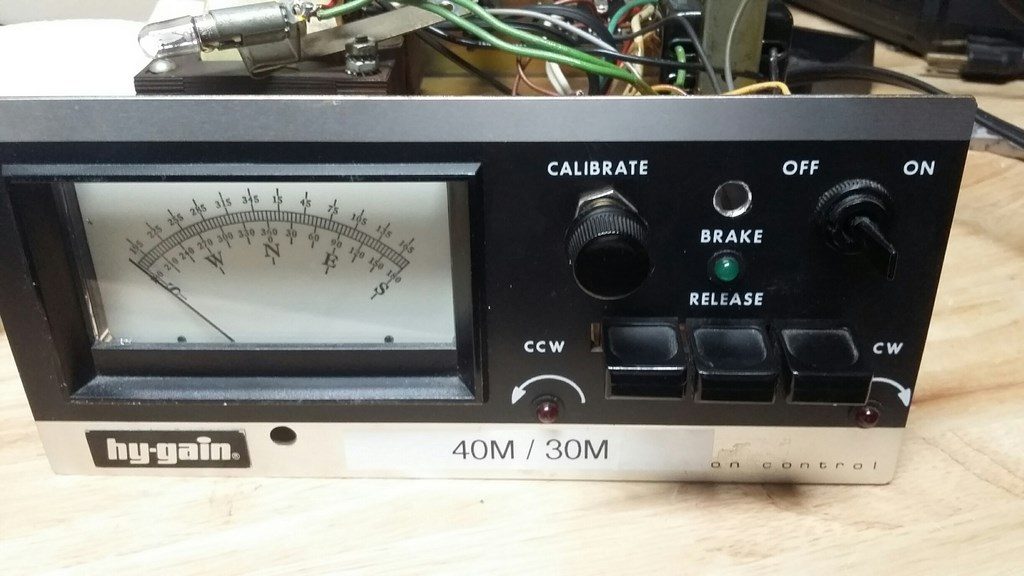
In my continuing efforts to implement more and more station automation into my primary operating position I recently decided to tackle my old HyGain controller used to control the Tailtwister rotator on my 40M Moxon tower. The primary goal was to add RS-232 computer control functionality. I looked into available options and settled on the Rotor-EZ solution from Ham Supply. Since I enjoy building I selected the kit form. The image below shows the kit as it arrives from Ham Supply.
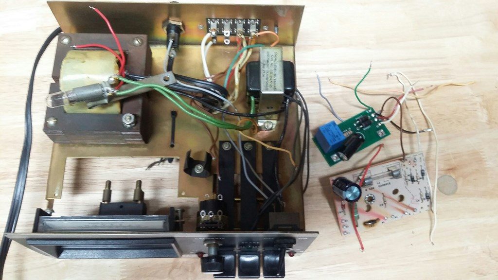
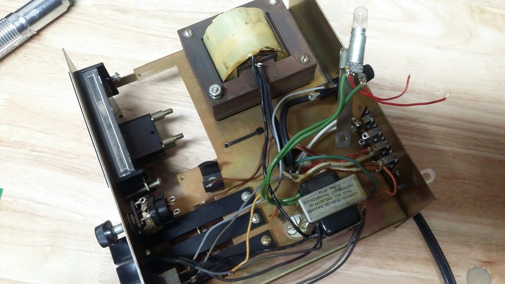
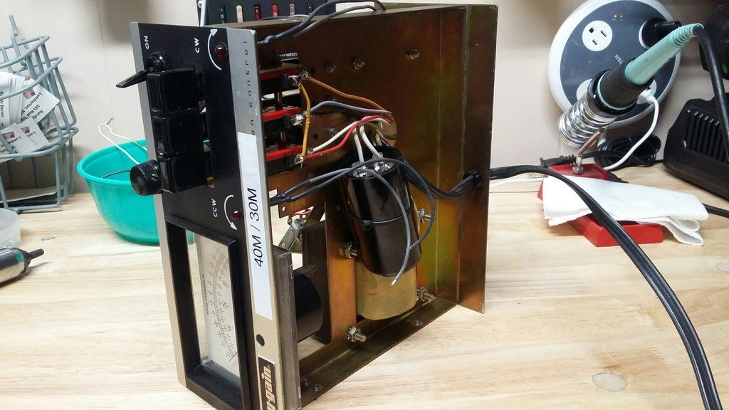
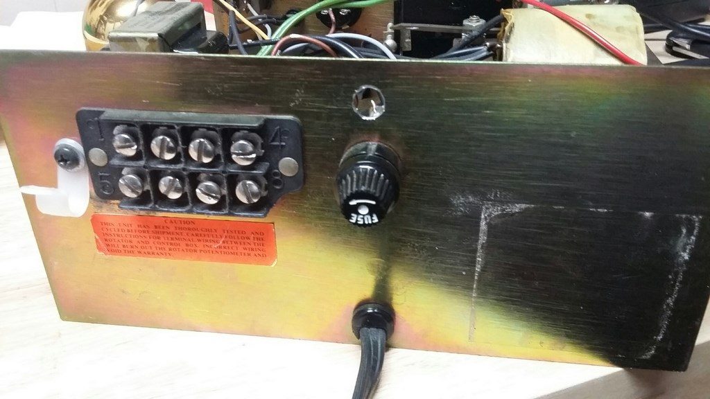
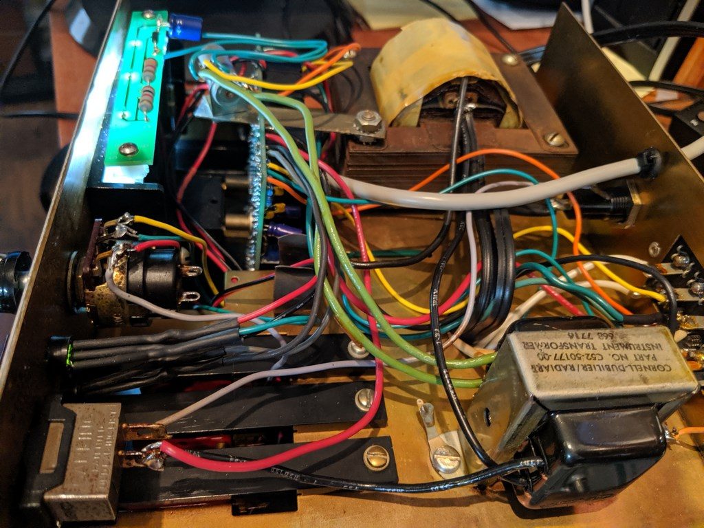
After completing a parts inventory and confirming that everything was there I began by removing the original guts of the controller. A paper copy of the step-by-step instructions comes with the kit but I highly recommend downloading the Word document version from the Ham Supply web site. The diagrams are clearer and you can enlarge the print as much as you need to. The 3 photos above show the controller with original electronics and wiring removed. Follow them closely throughout the upgrade process. The instructions give two options for mounting the PCB, either directly to the back of the meter (on the older controllers) or on the bottom of the controller chassis. If you have the newer style controller the bottom of the chassis is your only option. I have the older style controller and choose to mount the new circuit board directly onto the meter studs.
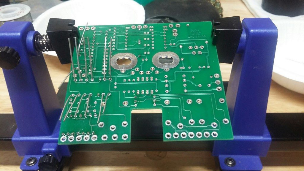
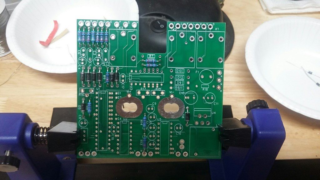
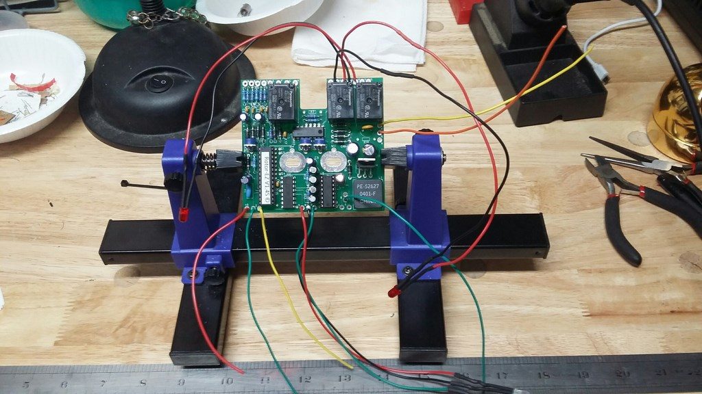
Once the old wiring and components were removed from the controller chassis it was time to start mounting and soldering the new circuit board components. An inexpensive PCB holder comes in real handy for this step. The one seen here in the photos was a pretty cheap eBay purchase and it did the job just fine. I used my variable temperature soldering iron set on about 380C with a very small chisel tip and Kester #44 .015 core solder. I like the extra fine solder when working on PCBs since I find it offers better control. When soldering some of the interconnecting wires to terminal lugs inside the control box I used my trusty Weller WP25 with a medium chisel tip to get more surface area and heat transfer.

Left photo above shows solder side of the PCB about 90% completed. Right photo shows completed PCB ready for the LEDs and other attachment wires to be soldered in place.
However, before doing that it was time to drill the holes for the new “Status” LED on the front panel and a hole for the RS-232 cable on the back. The hole for the Status LED is 1/4″ and the hole for the RS-232 cable is 5/16″. The supplied grommet for the cable is a little tight getting in-place, but it does fit if you just take your time and make sure you get the edges around the hole nice and clean with a deburring tool. Neither hole in the photos had been deburred when I took the picture.
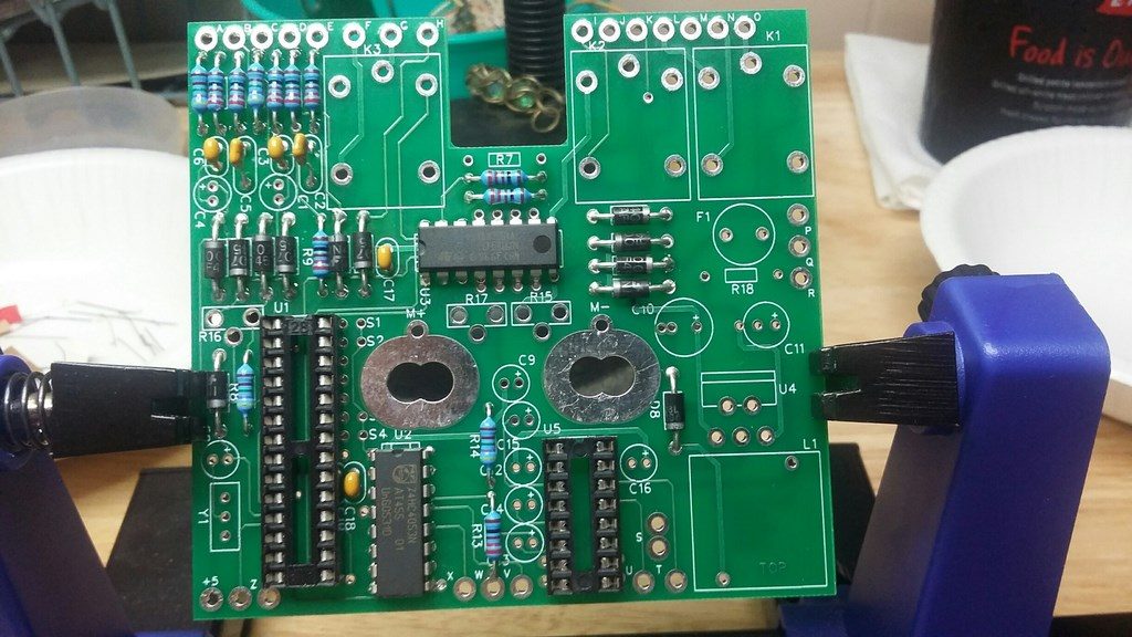
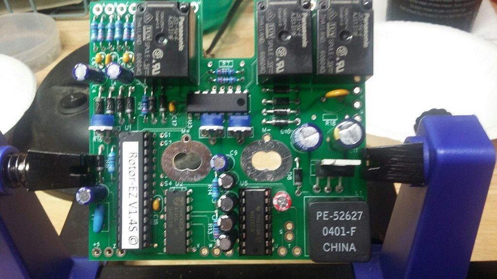
Left photo above shows the completed PCB with all interconnecting wires and LEDs attached and ready to mount into the chassis. Right photo shows the new PCB installed mounted to the meter studs. Note that at this point I had not decided to upgrade the stock incandescent lamp to LED. But you will also note the indentation right below the bulb socket indicating melting had occurred over the years. Not sure if this is typical or I just had the wrong bulb in but it didn’t look like a good idea and besides, those bulbs burn out pretty regularly and I had replaced it (maybe with the wrong one) 2 or 3 times over the years. Anyway, I ordered an LED kit from Ham Supply and it arrived within a few days.
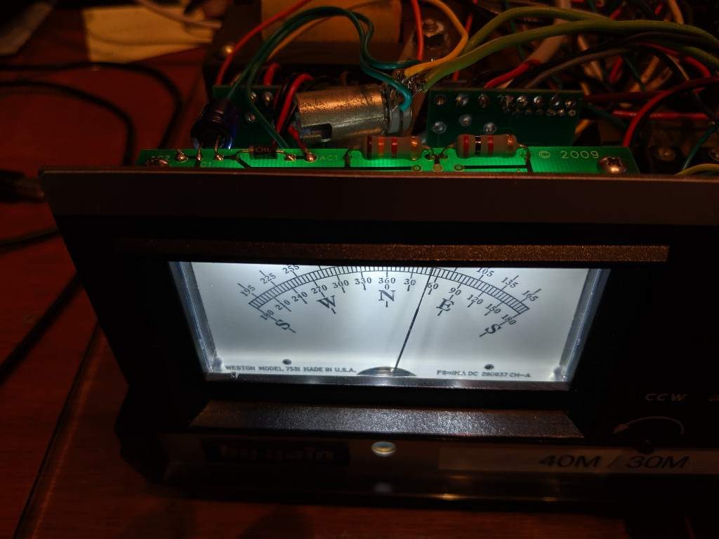
The LED light kit was a snap to put together. Note that I decided to just leave the legacy bulb holder in place and solder the wires from the kit right to there. It takes just a little moving around of the LEDs to find the “ideal” location to provide the best lighting of the meter face. Viewing mine straight on there are a few dark spots but overall I was very pleased with the result. It’s much brighter and easier to read than the original bulb.

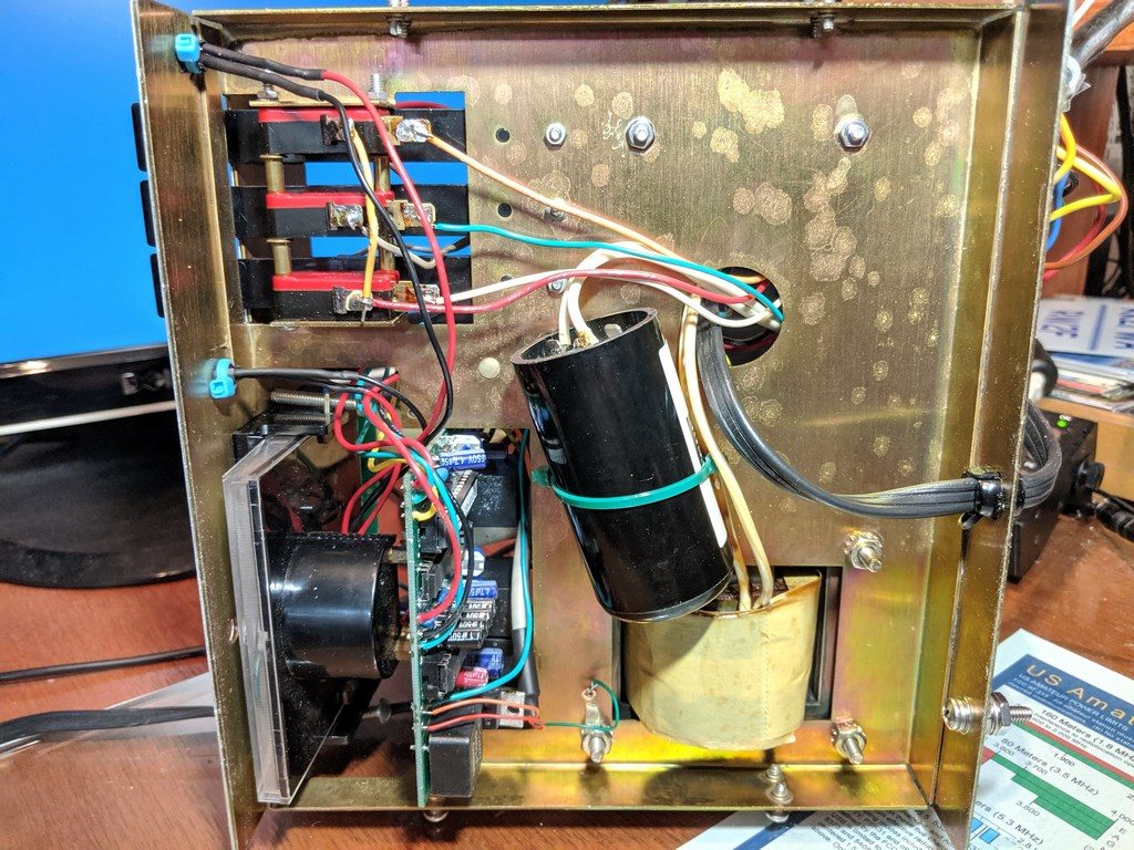
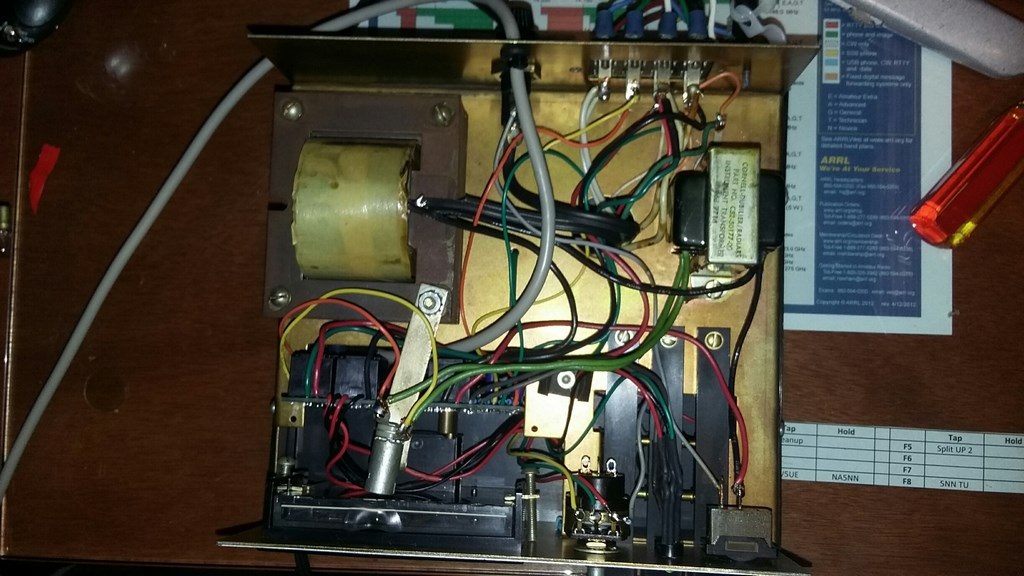
Throwing in these 2 photos so you can get a better view of the PCB mounting to the meter studs. Tightening the nuts on the studs was a bit tricky. I ended up temporarily removing the ty-wrap holding the big electrolytic to the bottom of the chassis so that I could move it out of the way and then get my nut driver on them enough so they could be turned.
And finally you can see a little YouTube video I did showing the upgrade in action. I’ll say up front that my video skills are very lacking, so forgive the poor quality. But, I think it gets the point across.